| |
| Pressure Action
Pumps |
| |
|
Pressure power pumps have been
part of our steam heritage since the early 1900's. Are you tired of paying
fulltime crews to repair or replace the same Electro-mechanical pumps over and
over?
Tunstall Pressure Action Pumps are the maintenance free
solution for peace of mind and long term savings. |
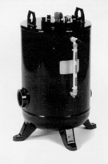 |
Tunstall AP-400 Series
Pressure Action Pump
The Tunstall AP-400 Series Pressure Action
Pump is the low maintenance, non-electric solution to move condensate or other
liquids from low points, low pressures or vacuum spaces to an area of higher
elevation or pressure. Condensate can be returned at temperatures well above
the 210° F limit of conventional problems.
| Features: |
| - |
Non-electric - utilizes inexpensive steam, air or gas to
operate the action pump |
| - |
Explosion Proof - Intrinsically safe |
| - |
Low Maintenance - No leaking seals, impeller or motor
problems |
| - |
All stainless steel internals |
| - |
Externally removable/replaceable seats - valve & seats
can be replaced or cleaned without removing pump cap from body |
|
| |
| Table 1-1 Series
AP-400 Pressure Action Pump - Piping Dimensions |
| Model Number |
AP-404 |
AP-406 |
AP-408 |
AP-412 |
| in |
mm |
in |
mm |
in |
mm |
in |
mm |
| Inlet Connection |
1 |
25 |
1½ |
40 |
2 |
50 |
3 |
80 |
| Outlet Connection |
1 |
25 |
1½ |
40 |
2 |
50 |
2 |
50 |
| Motive Pressure Connection |
½ |
15 |
½ |
15 |
½ |
15 |
½ |
15 |
| Vent Connection |
1 |
25 |
1 |
25 |
1 |
25 |
1 |
25 |
| Gauge Glass Connection |
½ |
15 |
½ |
15 |
½ |
15 |
½ |
15 |
|
| |
| Table 2-1 Series
AP-400 Pressure Action Pump - List of Materials |
| Name of Part |
Description |
| Cap, Body and Bolting |
Fabricated Steel 150 psi ASME Sec. VIII
Design "U" Stamp
Coded. |
| Cap Gasket |
Compressed Non-Asbestos |
| Inlet Valve Assembly |
Stainless Steel |
| Vent Valve Assembly |
Stainless Steel |
| Valve Assembly Washers |
Zinc-Plated Steel |
| Plug |
Steel |
Mechanism Assembly:
Float and Springs |
Stainless Steel |
*Series AP-400 available in all stainless
steel. Consult Factory. |
| |
| Table 4-1 Inlet
Reservoir Pipe Sizing For Closed Systems |
Condensate
Load
lbs/hr |
Reservoir Pipe Diameter (in) |
| 2" |
3" |
4" |
6" |
8" |
10" |
| up to |
Length of Pipe (feet) |
| 1000 |
4½ |
2 |
1½ |
|
|
|
| 1500 |
7 |
3 |
2 |
|
|
|
| 2000 |
9 |
4 |
2½ |
|
|
|
| 3000 |
13½ |
6 |
3½ |
2 |
|
|
| 4000 |
18 |
8½ |
5 |
2½ |
|
|
| 5000 |
|
10 |
6 |
3 |
1½ |
|
| 6000 |
|
12 |
7 |
3½ |
2 |
|
| 7000 |
|
14½ |
8½ |
4 |
2 |
|
| 8000 |
|
16½ |
9½ |
4½ |
2½ |
1½ |
| 9000 |
|
|
11 |
5 |
3 |
2 |
| 10000 |
|
|
12 |
5½ |
3 |
2 |
| 11000 |
|
|
13 |
6 |
3½ |
2 |
| 12000 |
|
|
14 |
6½ |
4 |
2½ |
Note: Inlet reservoir pipe sizing. When
draining condensate from a single piece of equipment in a "closed
system" to achieve maximum energy efficiency (see Fig. 2-2), a reservoir
should be installed horizontally above and ahead of the action pump. Sufficient
reservoir volume is required above the filling head level to hold condensate
during the action pump discharge cycle. The chart above shows the minimum
reservoir sizing, based on the condensate load to prevent equipment flooding
during the action pump discharge cycle. |
| |
| Table 4-2 Vented
Receiver Sizing for an "open system" |
| *Flash Steamlbs/hr |
|
Receiver
Diameter |
|
Receiver
Length |
|
Vent Line
Diameter |
|
| up to |
|
|
|
|
|
|
|
| 75 |
|
4" |
|
|
|
1½" |
|
| 150 |
|
6" |
|
|
|
2" |
|
| 300 |
|
8" |
|
36" |
|
2½" |
|
| 600 |
|
10" |
|
|
|
3" |
|
| 900 |
|
12" |
|
|
|
4" |
|
| 1200 |
|
16" |
|
|
|
6" |
|
| 2000 |
|
20" |
|
|
|
8" |
|
Important Note: Vented Receiver Sizing. When
draining from single or multiple pieces of equipment in a "open system",
a vented receiver should be installed horizontally above and ahead of the
action pump (See Fig. 2-1). In addition to sufficient holding volume of the
condensate above the fill head of the action pump to hold the condensate during
the action pump cycle, the receiver must also be sized to allow
enough area for flash steam and condensate seperation. An overflow could also
be added when required. The minimum recommended water seal is 12". The chart
above shows proper receiver tank sizing based on flash steam present. See chart
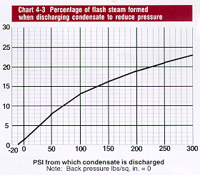
4-3 to calculate the % of flash steam at a given pressure drop. |
| |
 |
| |
Suggested
Specification
|
The non-electric condensate pump shall be
Tunstall International AP-400 series operated by steam, compressed air or other
pressurized gas up to 125 psig. Electricity, seals or packings shall not be
used.
AP-400 series body construction shall be of carbon steel and
vessel shall be ASME Section VIII "U" stamp coded.
Pump internals shall
consist of all stainless steel float operated mechanical mechanisms. Motive and
vent valve/seats shall be externally removable without removing cap from the
vessel body for ease of maintenance and inspection. |
|
| |

|
Home - Capsules -
Cross References - Savings - Thermostatic Traps
F&T Traps - F&T
Kits - Action Pumps -Bucket Traps - TD
Traps |
| |
|